
文章目录
Dashboard
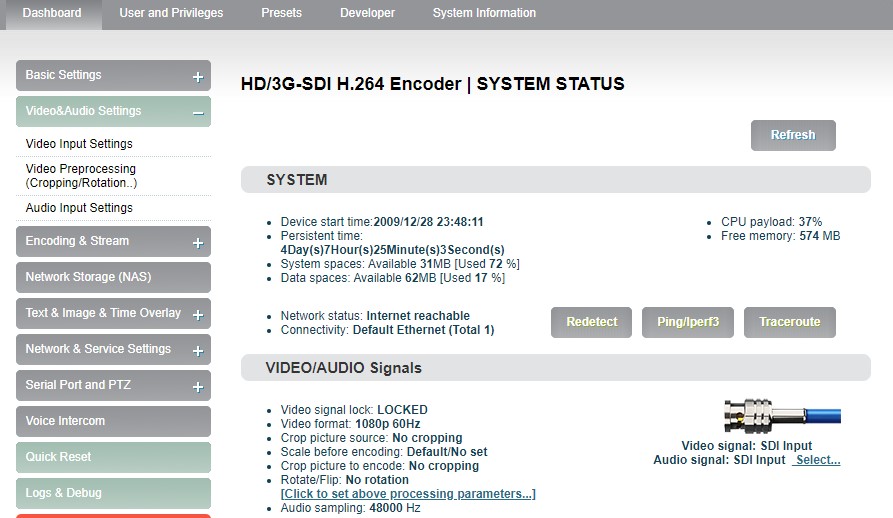
“Dashboard” is an overview of the current running status of the device and the status of audio and video streams. Users can click the “Refresh” button to refresh in real time, which can greatly help the encoder setting and troubleshooting.
System
Click “Basic Setting”, users can know information including “device start time”, “persistent time”, “system spaces”, “data spaces”, “network status” and “connectivity” of the device, and go for “Ping” testing. If users need to push to Internet platforms, network status should be “Internet reachable”, or it cannot push streams.
The “Ping” provides a simple function to test whether the network is reachable. Open the “Ping” button, enter the test address, click “Ping”, wait for 3s, and “Connectivity” is displayed as “reachable, packet loss rate 0%" means the network is good and streams can be pushed to the Internet normally.
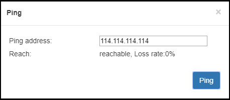
Note: If Ping public IP address is reachable, but Ping domain name is unreachable. Generally, it is because the DNS server configuration is incorrect.
Video/Audio signals
It can show “Video/audio signal”, “video format”, “preprocessing”, “audio sampling” as below:
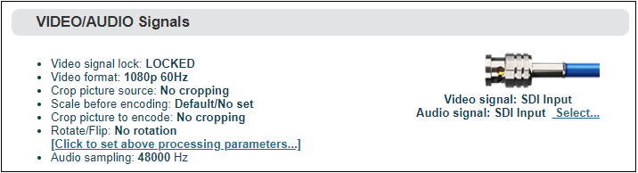
If “video signal lock” displayed as “no signal (display blue screen)”, it means the video input source is not detected by the device. Please check if the input cable is plugged in. If “Audio sampling” is displayed as “0Hz”, the audio signal is not collected on the device. Please check if the audio of the input source is normal.
Basic settings
Users can go for some basic functions settings here.
Change WEB login password
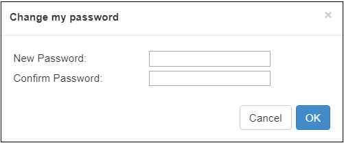
Click “Change Password”, an option box will pop up, users can modify the WEB login password, the default password is admin.
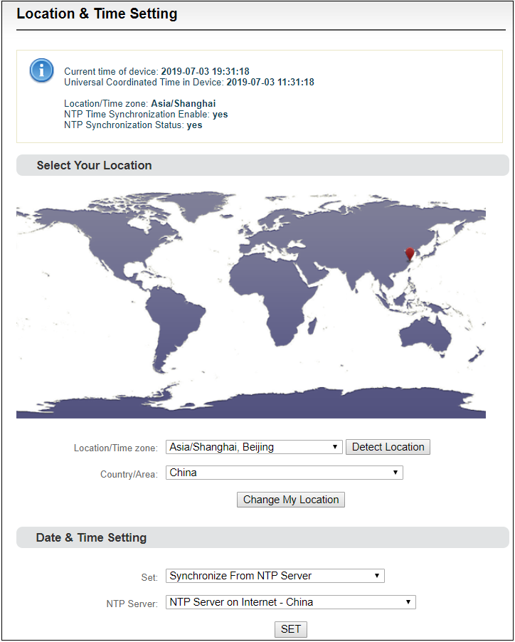
Location and time
Click “location and time”, then users can modify system time of the encoder, or just select “Synchronize from this PC”.
1.1.1 Restore factory settings
If users change parameters that lead encoder couldn’t work (Typical situation is that encoder couldn’t be visited by network after modifying network address), users could restore factory settings to default value.
Two methods for restoring factory settings:
-
Via the WEB interface, "Basic Setup > restore factory settings" function;
-
Through RESET button:
On the dashboard, there is a button of . Pressing on RESET button for 3 seconds, device will restore factory settings. Restoring factory setting will lead to the device hard restart, restarting course will last 1 minute.
Please note: after restoring factory setting, below parameters will be changed to default value:
●Login username and password will be admin;
●IP address will be restored as 192.168.1.168; subnet mask will be 255.255.255.0;
● All encoding parameters of video and audio will be restored to factory default value;
● Media transmission parameters will be restored as factory default value.
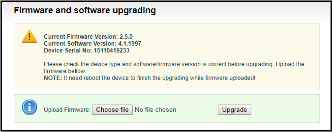
Firmware upgrading
The encoder supports online firmware upgrading. Through the “Basic Settings-Firmware Upgrade” of the Web page, users can upload the firmware online. Click “Select Files” to select the upgrade file, and click “Upgrade” to upgrade the device. The upgrade process is slow, around 30s to 1 minute, please be patient.
Video & Audio adjustments
Video source choice and adjustments
Users can choose video source, adjust brightness, contrast, saturation and hue parameters of the video here.
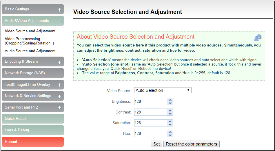
“Auto Selection” means the device will check each video source and automatically select the one which has signal.
“Auto Selection (one-shot)”same as “Auto Selection” but once it selected a source, it ‘lock’ this and never change unless you ‘Quick Reset’ or ‘Reboot’ the device!
The value range of Brightness, Contrast, Saturation and Hue is 0~255, default is 128. Based on the median value, the increase/decrease value corresponds to the increase/decrease in brightness/contrast/saturation. The default value of Hue is 128, which represents phase 0; the value range is 0-255.
Video preprocessing
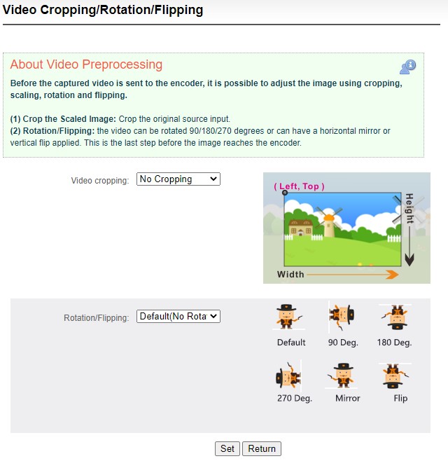
Before the captured video is sent to the encoder, it is possible to adjust the image using cropping, scaling, rotation and flipping.
(1) Crop the Scaled Image: Crop the original source input.
(2) Rotation/Flipping: the video can be rotated 90/180/270 degrees or can have a horizontal mirror or vertical flip applied. This is the last step before the image reaches the encoder.
Audio signal source
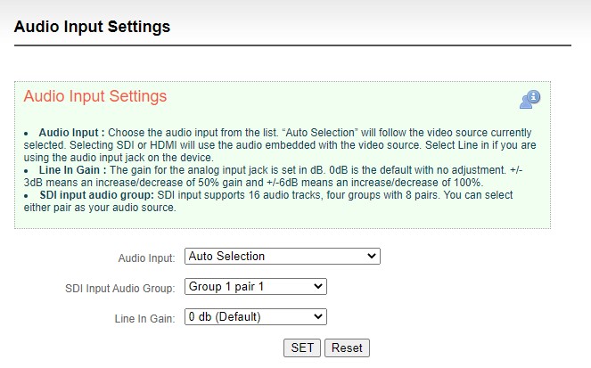
Audio Input : Choose the audio input from the list. “Auto Selection” will follow the video source currently selected. Selecting SDI or HDMI will use the audio embedded with the video source. Select Line in if you are using the audio input jack on the device.
Line In Gain : The gain for the analog input jack is set in dB. 0dB is the default with no adjustment. +/- 3dB means an increase/decrease of 50% gain and +/-6dB means an increase/decrease of 100%.
SDI input audio group: SDI input supports 16 audio tracks, four groups with 8 pairs. You can select either pair as your audio source.
Encoding & Steam
Audio encoding parameter setting
Encoders can set audio encoding parameters. Click “Encoding &stream”, pull downward “Audio Encoding Engine”, then entering into audio parameters setting. Audio encoding channel is forced to enable. Audio encoding modes include AAC and G.711, optional. Audio sampling is chosen according to actual situation. Channels consist of “Stereo” and “Mono”. Encoding bitrate is adjustable between16K-256K, default is 64Kbps. One more detail: if encoder using TS-UDP protocol or needs using recording, then it needs to choose “With ADTS header” under AAC format.
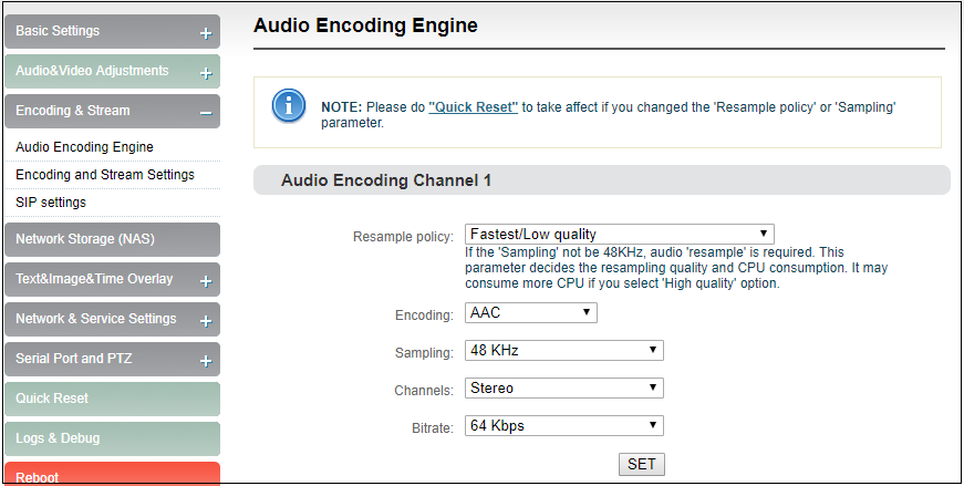
Note: Please do "Quick Reset" to take affect if you changed the ‘Resample policy’ or ‘Sampling’ parameter.
Encoding and stream settings
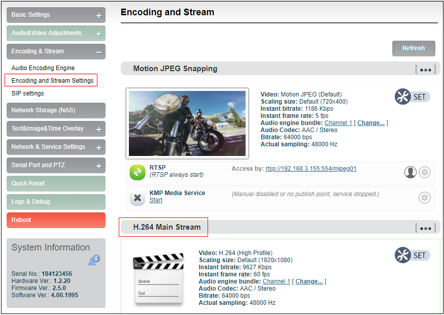
Video encoding parameters are adjustable. Click “Encoding &Stream”, pull downward “Encoding and stream settings” to enter below interface. We generally set parameters of “H.264 main stream”, click “Setting”.
Note: It is H.264 Main stream, the second setting, not Motion JPEG setting.
Click SET, entering into below interface for main streaming encoding parameters setting, as follows:

“Scaling” has 9 options for choice. Default setting is “Default size”, that is, the video size after encoding is the same as the input video size.
“Color” has two options: “With color and monochrome”. Monochrome is black and white color, “with color” remains the original color. Default setting is “With color”.
“H.264 Profile” supports High profile,main profile,baseline, which is set according to platform supported encoding profile. High Profile is the highest compression efficiency, that is, under the same bitrates, image quality is the best; Baseline is the most widely supported; default setting is High Profile.
“Bitrate control” has two ways: CBR-Constant bitrate and VBR-Variant bitrate. From literal meaning, CBR is stable and unchanged bitrate, while VBR is constantly changing according to actual content. Generally, network transmission adopts CBR to guarantee transmission quality, while file storage uses VBR to guarantee file quality. Default setting is CBR-Constant bitrate.
“Bitrate” supports adjustable 64K-25M. Users could choose default setting, or self-define bitrate size. The higher bitrates, video quality after encoding is better. But specific setting should be based on actual network situation, couldn’t be higher than your own upstream bandwidth.
“Framerate” has three options: FULL (same as input source, HALF (half when source framerate>=50 and customized framerate. “FULL” means framerate after encoding is the same as the framerate of input source; “HALF” means if input video is 1920*1080P50, video framerate after encoding will be 25. This will be a good saving on the consumption of network bandwidth; customized framerate is user assigning framerate after encoding, in theory, it shouldn’t be higher than original framerate.
“GOP size” has five options and supports user-defined adjustment. It is adjustable according to actual situation, default is 60, and normally it could meet the most majority of needs.
“Reference frames” has two options: one and multiframes. Theoretically using multiframes can improve encoding quality, but some decoders and players may not support multiframes.
Sub stream parameter setting refers to Main stream configuration.
Streaming media service
Encoder currently support streaming services include: RTSP, RTMP push, HLS service, TS-UDP push ,SRT push, Onvif service. One code stream can run up to 8 stream services at the same time for the encoder, which means it can push the video stream to 8 different live platforms. There are two code streams (the main stream and sub stream) for the encoder, so the encoder can stream up to 16 different live platforms at the same time. In general, the main stream is enough, and the sub stream is mainly used in the security monitoring field to achieve the docking usage with the NVR.
Motion JPEG stream
Encoder has a Motion JPEG stream, it keeps running without stop. It is blank with blue color if without video access. If with a video signal access, Motion JPEG stream will display the content of current flow, “the video signal lock” displays locked and it will display the current video signal format.
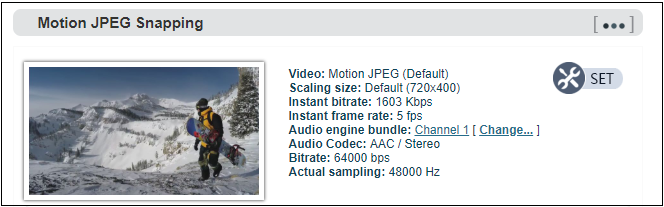
Note: Motion JPEG stream is a picture preview, refresh every 3 seconds, or click the mouse to refresh, so it is normal to see it is not fluent on the page.
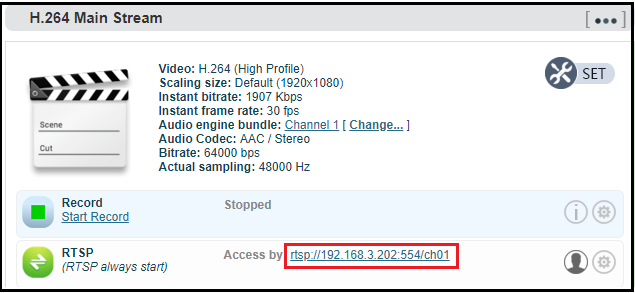
RTSP service
RTSP service cannot stop when encoder runs. It will not have additional load on the encoder if the stream is not pulled for decoding. As shown in the red frame, the RTSP service flow address is "rtsp://192.168.1.168:554/ch01". "192.168.1.168" is the IP address of the encoder, If the for encoder, the IP address is 192.168.2.168, then the RTSP service address is "rtsp://192.168.2.168:554/ch01", if there are several IP encoding device, these IP address can also directly pull RTSP flow accordingly.
Normally VLC media player is used to decode and play the video stream. Open VLC media player, select the "media", and "open network stream", then enter the RTSP service URL address, you can play the video.
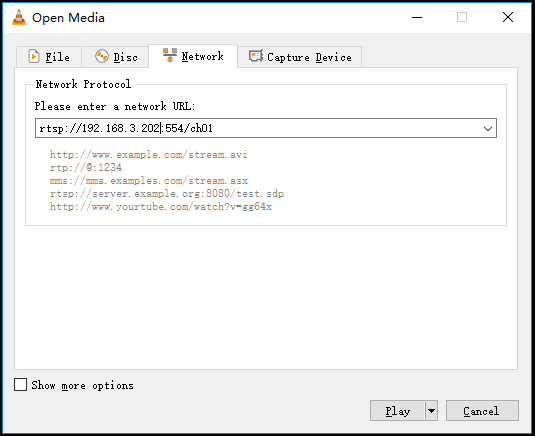
Note: URL should be copied completely and the punctuation marks should be included.
RTMP Pushing (Live streaming)
Using RTMP pushing, the first thing is to make sure platform providing RTMP pushing address, otherwise our encoders couldn’t do RTMP pushing (Currently some live streaming APP couldn’t provide RTMP pushing address.)
Note: The principle of RTMP push stream is that it must be pushed from the encoder to the platform. The computer/decoder then pulls the RTMP stream from the platform for playback. The encoder cannot directly push the RTMP stream to the computer/decoder for playback.
YouTube live streaming
“Streaming point” is RTMP address given by platform (Take YouTube as an example). (Other platforms are similar, if any questions please contact platform technical support for help).
1) Login to YouTube, get below address:
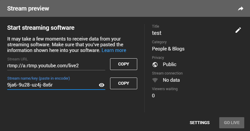
Streaming point should be like Server URL+Stream name/key.
For example: rtmp://a.rtmp.youtube.com/live2/9ja6-9u28-uz4j-8x6r
2) After you get the RTMP URL address, you need to set it up in the encoder. In the main stream of H.264, there is a stream service option to be added. By adding a RTMP push, you can get a RTMP push option. Click the settings button on the right side of the RTMP push, and you will enter the interface to fill in the RTMP push configuration. The push address on YouTube platform is filled in the "push point", and set "Enable pushing" to "Yes". Click “Save”, then RTMP will stream to YouTube.
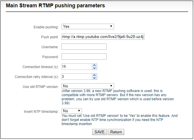
If the platform requires user name and password verification, you also need to fill in the corresponding parameters in the encoder.
3) On YouTube platform, if the video can be displayed, the push stream is successful; otherwise you need to check the network and other configurations.
Note: In the case of RTMPS push mode, fill in RTMPS URL at Push point and set ‘Use old RTMP version’ to yes, so that it can be supported.
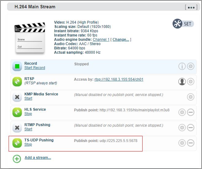
1.1.1.1 TS-UDP Pushing (unicast and multicast)
Click  to select TS-UDP Pushing, then entering into TS-UDP setting interface.
TS-UDP pushing divides into unicast and multicast. If using unicast, “pushing target address” is device IP address of receiving TS streaming. “Target port” is any port, but it is better not conflicted with other service port. No need to change Multicast TTL; If using multicast, “pushing target address” needs to write a correct multicast address (224.x.x.x ~ 239.x.x.x). “Target port” is any port, but it is better not conflicted with other service port.
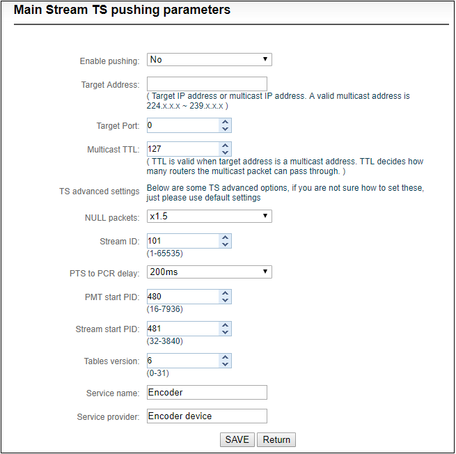
After finishing setting, it will come up an URL address from TS-UDP pushing, which could be decoded through VLC or other decoding player. If it is multicast, please remember to close Windows firewall.
Note: When the URL obtained by configuring multicast push mode is udp://225.225.5.5:5678, if played by VLC Player, it needs to add @ for playing, that is udp://@225.225.5.5:5678.
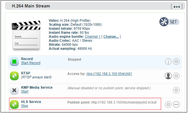
HLS service
Using HLS service, the first thing is to “add a stream service”, then click right-side SET icon of “HLS service” for setting.
Below is setting interface of HLS service. Very simple, if no special requirements, no need setting, only enable service.
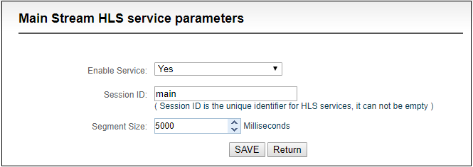
Once enabling service, it will get one HLS Publish point. You could watch it through VLC and other players using this address.
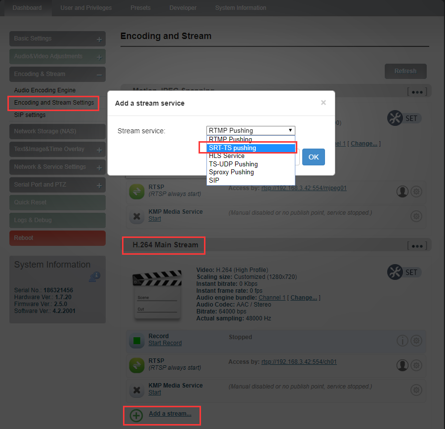
SRT-TS pushing
1.Click “Encoding & Stream”—“Encoding and Stream Settings” –“H.264 main stream” –“Add a stream”. Choose “SRT-TS pushing”, click “OK” and add a SRT service.
2.Click the icon  for SRT configuration.

3.Fill in the pushing address and port, click “Save”. Then SRT pushing is working.
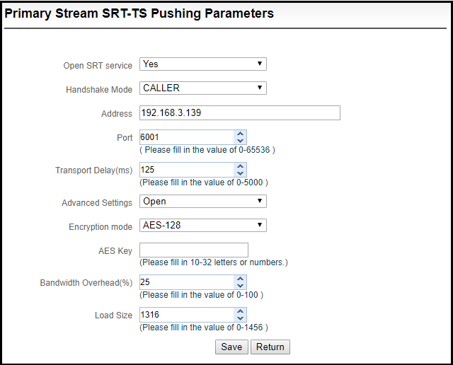
Handshake mode: Caller、Listener、Rendezvous;
Address: Set IP address of the receiving port;
Port: Set the listening port corresponding to the receiving port;
Transport delay: Set it based on the performance of the current network, the delay value can be set on both the SRT source device and the SRT target device. The final SRT transmission delay will be the larger one of the two values. Default is 125ms;
Advanced settings: Open and Close;
Encryption mode: AES-128, AES-192, AES-256;
AES key: encryption AES key can be 10-32 letters or numbers combination;
Bandwidth overhead: It is set as the percentage value based on network link quality. Using this value to multiply the total bitrate of the audio and video encoded by the encoder, this will get the occupied maximum bandwidth allowed by Bandwidth Overhead. This value plus the total of video and audio bitrate is the threshold of the current SRT transmission bandwidth, and also the maximum bandwidth that SRT stream can be used. From the perspective of "overhead", it is the extra "invalid" bandwidth to be used in addition to the media content required for transmission (which can be understood as the payload), but it is different from our common protocol overhead, TCP header overhead, UDP header overhead. The bandwidth overhead here is not a fixed 20~60 bytes TCP header overhead or 8 bytes UDP header overhead. It changes in real time according to the network conditions. The worse the network link conditions are, the more overhead needs for normal transmission. The range is 5%~100%, and the default overhead is 25%;
Load size: Sending data packet size, it is optimal that the receiving port should equip with the same size. The default size is 1316, the optimal packet for the codec.
| Network highest packet loss rate (%) | RTT Multiplier | BW Overhead | The lowest SRT delay (when RTT≤20ms) |
|---|---|---|---|
| ≤1 | 3 | 33 | 60 |
| ≤3 | 4 | 25 | 80 |
| ≤7 | 5 | 20 | 100 |
| ≤10 | 6 | 17 | 120 |
Note: Below format is the reference delay value under different packet loss. When RTT>20ms, it requires to increase the delay appropriately.
- Save the settings, then a SRT-TS pushing address will be added. The encoder starts to initiate a handshake connection to the receiving port.
Local recording
Encoders support local recording function. Encoder with TF card-slot can support TF recording and meanwhile it supports USB disk inserted into USB port of encoder for recording. The recording operation is as follows:
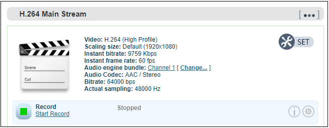
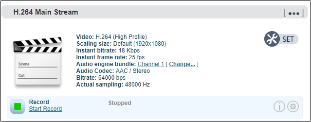
1.Click “Record” below “H.264 Main Stream” under “Dashboard” or “Encoding and stream setting”.
2.Click  “Record settings” icon for setting
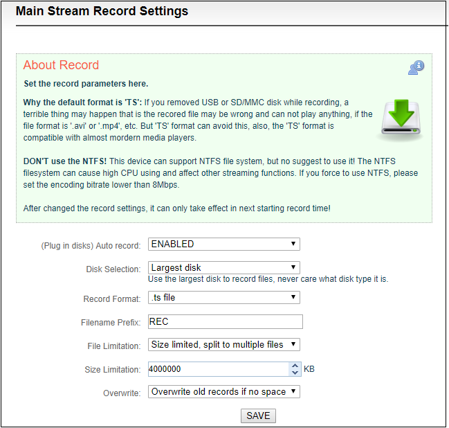
Note: A real challenge for recording by removable disks: If you remove the storage disk while recording, the recorded file may be wrong and can not be played if the file format is ‘.avi’ or ‘.mp4’, etc. But ‘TS’ format can avoid this, also, the ‘TS’ format is compatible with almost all the main media players.
If recording is performed in a non-TS format, when the recording is completed, stop the recording manually, and then remove the storage device to ensure the recording can be played normally.
3.By default, it automatically starts recording when storage disks inserted, regardless its storage type. It will record to the biggest available storage area. Recording format is TS file by default. Users could set recording for automatic cutting based on specified size. And when storage space is insufficient, it will automatically overwrite the old video file to achieve redundant storage.
4.Click  to check recording status and record list.
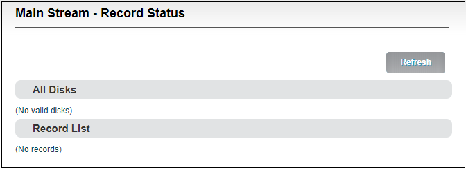
When no disks inserted or NAS network storage not set, the status will be as follows , dashboard will show “Stopped”.
Record status shows “No valid disks” and “No records”.
After inserted disks, the encoder will start recording automatically and the dashboard shows “Recording”.
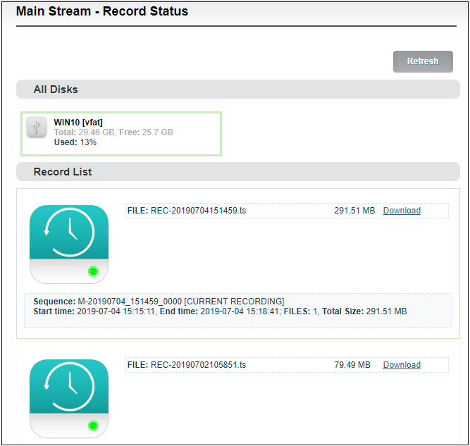
The "Video Status" is shown below, where you can view the usage of the memory or downloads the video files that have been stored in the memory to the computer.
When it is recording, users can stop the recording manually and it can be restartedagain.
Note: When recording with TF card, it only supports formats of NTFS, FAT32 or vfat. For TF cards over 64G, the default formatting is exFAT under the formatting program of Windows system, which may lead to the TF card unrecognizable.
Sometimes, due to the influence of some files or programs in the TF card, the TF card can not be recognized. You need to format the TF card once.
Network Storage(NAS)
NAS is a Disk Arrays connected by network; it has all the main characteristics of disk arrays: high capacity, high efficiency and high reliability.
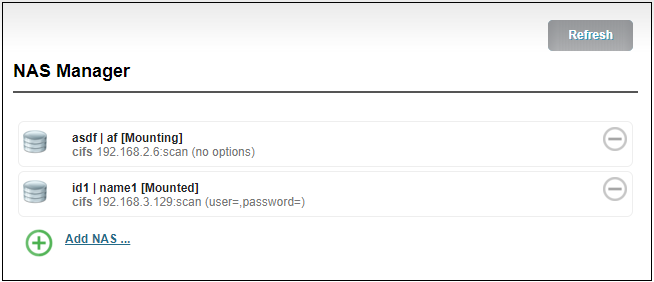
Open NAS Manager, click “add NAS”, then fill in the corresponding parameters.
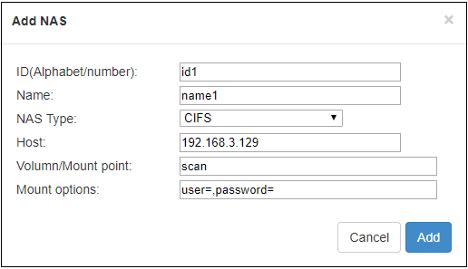
ID/ Name: Any Alphabet/number.
NAS Type: NFS or CIFS (CIFS is a shared protocol for network connection, which requires high reliability of network transmission, TCP/IP is usually adopted; NFS is transport-independent,TCP or UDP is adopted; One of the disadvantage of NFS is, it requires the user to install a special software, while CIFS is integrated inside the OS, and no additional software is needed.).
Host: IP address of the Host.
Volume/Mount point: Storage location on the host.
Mount options: Settings about the user name and password.
NAS manager will show “Mounted” if NAS connection has been established, and there is a RECORD file under the Mount point. If the connection is abnormal, it will be displayed as “Mounting”.
Text/ Image/Time overlay
Please open the “Overlay image management” to upload an image first if you want to make image overlay; if text or time overlay, you can set the overlay function directly.
Overlay Image Management
Enter “Image Management” —fill in “Image ID– Choose the image that you want—click “Add”, then image is uploaded to the Encoder storage. You can check the image and information listed under the Image list.
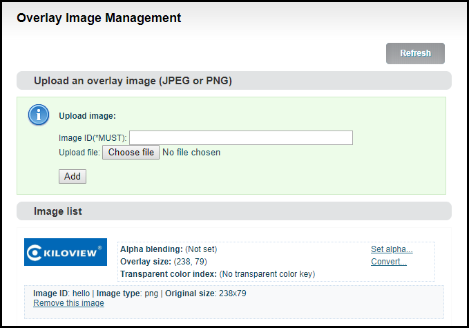
You can change the parameters after uploading the image
Set alpha blending: Value range is 0-255, 0 is full transparent and 255 is no alpha blending.
Convert:
Image size: If width/height set to 0, it will overlay the image as original size.
PNG transparent threshold: If the original PNG transparent level is less than the threshold value, overlay that area as full transparent. Set a reasonable value can make the image border be smooth.
Transparent color index: Manually specify an index color to erase background. Set tolerance (0%~100%) to control the similar color range selection. In most cases, transparent PNG images do not need to be processed manually.