S2 encoder currently supports streaming services include: SRT/NDI|HX/ RTSP/RTMP/HLS/TS-UDP. One code stream can run up to 8 stream services at the same time for the encoder, which means it can push the video stream to 8 different live platforms. There are two code streams (the main stream and sub stream) for the encoder, so the encoder can stream up to 16 different live platforms at the same time.
文章目录
NDI|HX
S2 currently supports NDI|HX2, default is opening in the streaming service, click [on] to open or close NDI|HX stream service.

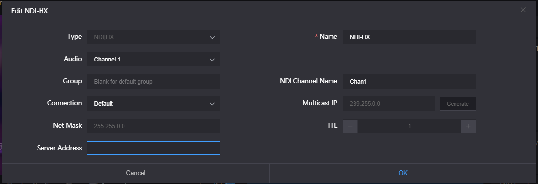
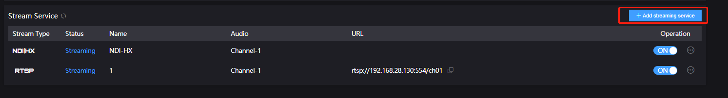
Click setting button in the end of stream service for stream configuration.
Name: Name for user-defined, Chinese, English and figure symbol supported.
Audio: You can choose the audio channel name set on the audio parameter page for audio encoding. The audio parameter configuration can be created by referring to chapter 6.2.3.
Group:To configure the devices to a group, the name of the group can be the combination of characters and figures. To configure multiple groups is allowed and the group names should be separated by comma (,). The default group name is “public”. You could set a specified group name, other devices need to search this device through specified group name, which avoids being searched at will by other devices via internet.
NDI channel name: When there are multiple NDI sources in the same network, you can modify the channel name with different parameters to identify each device correctly.
Connection:Two ways of connections: unicast and multicast. Default is unicast for transmission. Unicast is for one-to-one communication between devices, while multicast is device to a group communication mode, that is to say, device that joined in the same group can receive all the data from device.
Server address: You can register the discovery of source in the discovery server. For operation steps, you can refer to the discovery server chapter.
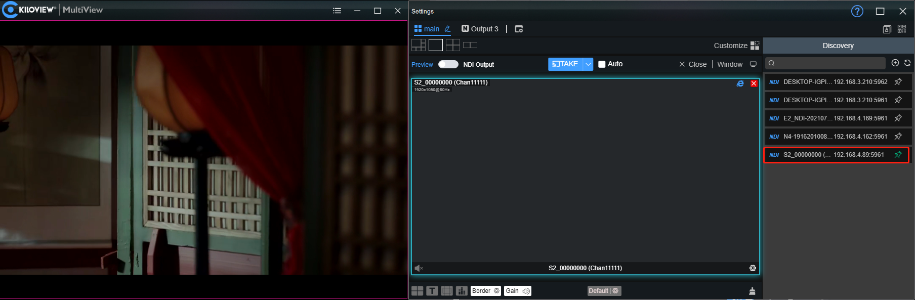
After configured, you can discover and output through NDI connected software. You can distinguish different NDI source through device name and channel name.
NDI discovery server
The NDI discovery server can replace the NDI discovery function with a server. The NDI sources are registered to the server, then the receiving end can get the NDI sources from the server. Or configure the function to send the output streaming to the receiving end.
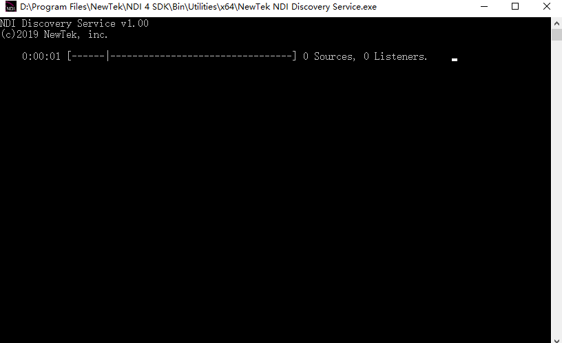
Enter the NEWTEK website (https://ndi.tv/sdk/) on the computer serving as the server to download and install the NDI SDK. After installation, run the file: Bin\Utilities\x64\NDI Discovery Service.exe
The NDI encoder configures the receiver IP address in the discovery server, and it will be registered to the server. It is recommended that the receiver IP address be configured as a static IP address to prevent the disconnection due to IP reassignment.
Click "discover server" on the decoder webpage to enable the function, and configure the discovery server IP address to the IP address of the computer. Then the NDI streams are registered to the server in the receiver.
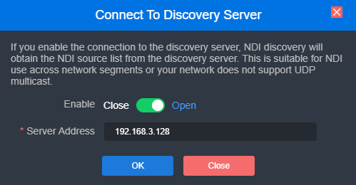
Note: After enabling the discover server, the mDNS auto-discovery function is invalid. The output streams from the encoder can only be sent to the designated server, and the receiving end must register to the same discovery server to pull the NDI streams.
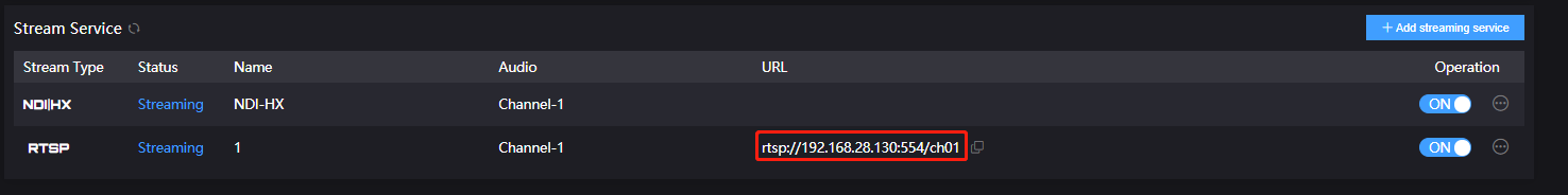
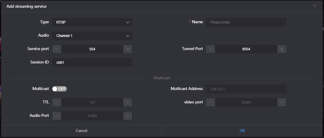
RTSP
Add an RTSP stream in the encoder, if it is not decoded and there will be no additional load on the encoder. As shown in the below, if the IP address of the encoder is 192.168.2.33, then the stream address of the RTSP service is rtsp://192.168.2.33:554/ch01. That is, you can directly pull as many RTSP streams as IP addresses the encoder has.
Under the same LAN, you can pull RTSP streams by VLC on the computer to test whether the encoding is normal and view parameter information, etc. After installing and enabling VLC, click "Media"-"Open Network Streaming" and fill in the URL of the encoder’s RTSP service, and it can be displayed.
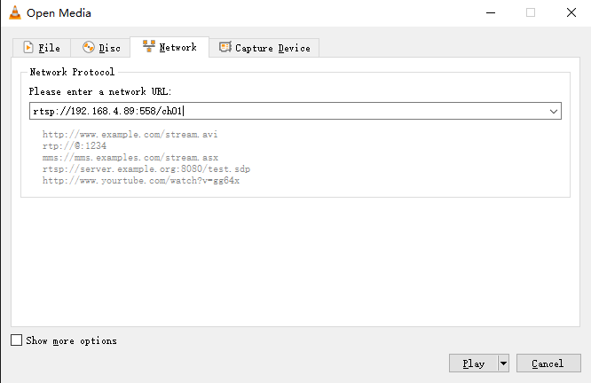
Note: The URL content needs to be copied completely, and the punctuation cannot be missing.
SRT
1)Click  to add a SRT stream service.
2)Fill in the pushing address and port, click “Save”. Then SRT pushing is working.
Setting parameters means the following (It can be set according to the network situation, and select the default configuration generally):
Ø Handshake mode: Caller, Listener and Rendezvous. The Caller and Listener mode are commonly used. In the LAN, the encoder and the decoder can use the Caller and the Listener at will. After one end uses the Caller mode, the other end uses the Listener mode. In Internet transmission, the one end with the public IP address will be the Listener;
Ø Public IP address: Set IP address of the receiver;
Ø Port: Set the listening port corresponding to the receiver;
Ø Transport delay: Set it based on the performance of the current network, the delay value can be set on both the SRT source device and the SRT target device. The final SRT transmission delay will be the larger one of the two values;
Ø SRT streaming ID: SRT streaming identification;
Ø Encryption mode: AES-128, AES-192, AES-256;
Ø AES key: Encryption key can be 10-32 letters or numbers combination;
Ø Bandwidth overhead: It is set as the percentage value based on network link quality. Using this value to multiply the total bitrate of the audio and video encoded by the encoder, this will get the occupied maximum bandwidth allowed by Bandwidth Overhead. This value plus the total of video and audio bitrate is the threshold of the current SRT transmission bandwidth, and also the maximum bandwidth that SRT stream can be used. From the perspective of "overhead", it is the extra "invalid" bandwidth to be used in addition to the media content required for transmission (which can be understood as the payload), but it is different from our common protocol overhead, TCP header overhead, UDP header overhead. The bandwidth overhead here is not a fixed 20~60 bytes TCP header overhead or 8 bytes UDP header overhead. It changes in real time according to the network conditions. The worse the network link conditions are, the more overhead needs for normal transmission. The range is 5%~100%, and the default overhead is 25%;
Ø Load size: Sending data packet size, it is optimal that the receiver should equip with the same size. The default size is 1316, which is the optimal packet for encoding and decoding.
| Network highest packet loss rate(%) | RTT Multiplier | BW Overhead | The lowest SRT delay (when RTT≤20ms) |
|---|---|---|---|
| ≤1 | 3 | 33 | 60 |
| ≤3 | 4 | 25 | 80 |
| ≤7 | 5 | 20 | 100 |
| ≤10 | 6 | 17 | 120 |
Note: The data in the form is the reference delay value under different packet loss. When RTT>20ms, it requires to increase the delay appropriately.
3)After configuration saved, a publishing point pushed by SRT-TS will be added, the encoder will initiate a handshake connection to the receiving end.
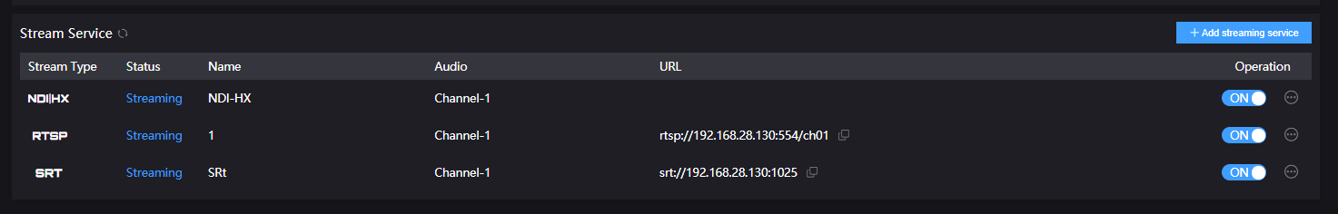
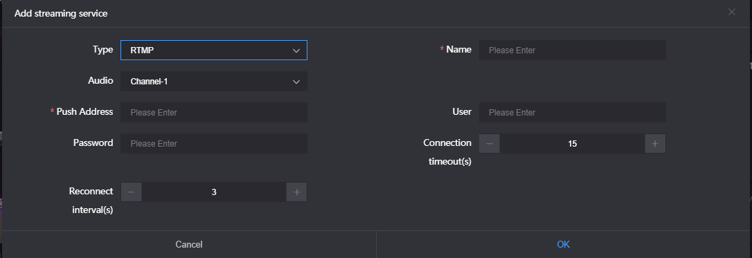
RTMP pushing (live streaming)
Using RTMP pushing, the first thing is to make sure platform providing RTMP pushing address, otherwise our encoders couldn’t do RTMP pushing.
Note: The RTMP pushing must be pushed from the encoder to the platform. The computer/decoder then pulls the RTMP stream from the platform for playback. The encoder cannot directly push the RTMP stream to the computer/decoder for playback. While Kiloview decoders support RTMP server functions.**
1)YouTube live streaming
“Streaming point” is the RTMP address given by platform (Take YouTube as an example).
Login to YouTube, get below address:
Streaming point should be like Server URL+ Stream ID/key,
For example: rtmp://a.rtmp.youtube.com/live2/9ja6-9u28-uz4j-8x6r
2)After getting the RTMP URL address, login to the webpage of the encoder, and click “Add a stream service” to add a stream under the “H.264 main stream”. Select RTMP in the pop-up window and fill in the URL address into the push address (The format is: rtmp address/live code), and then click “OK”. If the pushing is unsuccessful, please check the network of the encoder.
3)If the video can be displayed on YouTube, the pushing is successful, otherwise please check the network and other configurations.
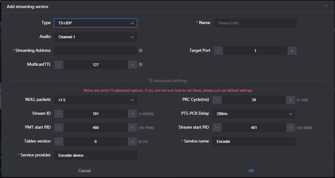
TS-UDP Pushing (unicast and multicast)
Click “ + ” to add a stream service and selects “TS-UDP pushing”.
The TS-UDP pushing includes two ways: unicast and multicast. If use unicast, the "Push Target Address" is the IP address of the device that receives the TS stream, and the "Target Port" is a port that not conflict with the ports of other services, and the "Multicast TTL" does not need to be modified. Unicast pushing can only be decoded and played at the target address; if use multicast, fill a correct multicast address (address range: 224.xxx ~ 239.xxx) in the "Push Target Address". "Target Port" is a port that not conflict with the ports of other services. For other parameters, if there is no special requirement, it is recommended to use the default values.
Note: Multicast streams can only be decoded and played under the same network segment. Both the encoder and the player need to be configured with a gateway.
After finishing setting, it will come up an URL address from TS-UDP pushing, which could be decoded through VLC or any other decoding player. If the multicast is decoded and played on the computer, please remember to close firewall and configure the network with a gateway.
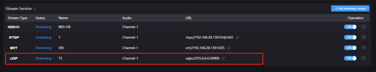
Note: When configure the multicast and get the URL is udp://225.6.6.6:1234. If use VLC Player to play, please insert an @ in the URL, that is, udp://@225.6.6.6: 1234.
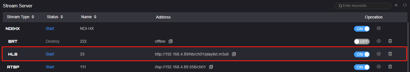
HLS service
Using HLS service, the first thing is to “add a stream service”, enter streaming service interface after added correctly.
HLS service setting is very easy, if no special requirements, no need setting, only enable service after entered name and clicked ok.
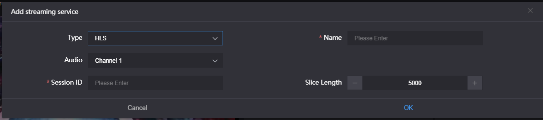
Once enabling service, it will get one HLS Publish point. You could watch it through VLC and other players using this address.